70CM MOXON BEAM
Introduction.
The 432MHz band used to be one of my favourites. In the early 1980s I owned one of the first FM321 70cms synthesised 4W FM transceivers (based on an Australian CB radio) and with this and an old Jaybeam 48el TV antenna mounted vertically on a pole and turned by hand on the side of the house I was able to work lots of local repeaters and some decent inter-G DX on FM simplex when there was "a bit of a lift on". 70cms has localised lifts every few days and that was part of the magic of the band: one day you could hear just locals and the next (in just one direction maybe) more distant repeaters or simplex stations could be heard or worked. Every day was different. Occasionally the band would be wide open and some super DX could be heard or worked. In those days I did not have any SSB transmitting gear on the band but I did listen in contests and at other times and well recall hearing an OZ station running 10W to an HB9CV antenna and being a true 59+ signal on a small indoor beam in the bedroom. The band is excellent for tropo DXing but it is much under-used nowadays. Fortunately there is still activity during contests and on Aug 3rd 2008 there was the RSGB 70cms low power contest restricted to stations running 25W or less. For a change I wanted to have a go /P but the problem was I had no beam antennas for the band just a the vertical colinear fixed on the side of the house. So, a check on the net showed up a design for a Moxon 2el yagi using a coat hanger! A quick search through my wife's wardrobe turned up a suitable metal one and 30 minutes of relaxing sawing, bending and straightening in the back of the garage resulted in a somewhat "Heath Robinson" 2 element antenna attached on the end of a 2m long plastic conduit tube. Connection between the coax and the feedpoint was via a small terminal block and the insulator between director and driven elements by a piece of PVC insulation grabbed from some 2 core cable. The whole antenna was supported on the pole using a support bracket made from a remaining piece of the coat hanger.
The Moxon Antenna Design.
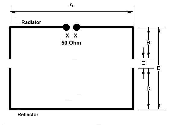
The Moxon antenna was designed by Les Moxon G6XN and is an optimisation of an earlier Australian design for a compact 2el beam. Essentially it consists of two metal or wire elements: (1) a driven element with its ends bent back towards the reflector (2) which has its ends bent towards the driven element. The entire antenna therefore forms a rectangle but occupying a space much smaller than a corresponding unbent 2el beam such as the HB9CV. The antenna is broadband, has a broad (100 degrees) front lobe, a good front-to-back ratio and a useful amount of forward gain and presents a decent near 50 ohm match at resonance. On HF these properties allow a small, lightweight beam to be erected with excellent performance for the size. On VHF/UHF it allows a smaller alternative to the popular HB9CV antenna with almost as much gain.
Testing.
I have no test gear for 70cms other than my FT817 and a power meter so I had to check the antenna using these. The SWR meter on the FT817 suggested the match was not brilliant (2 bars, which is about 2:1?) but not bad. A quick test using the local repeater with the antenna mounted vertically was successful and suggested some directionality. So, the next stage was to get out on the Sunday morning with the antenna and the 5W FT817 and see how it performed.
Results.
A local highspot was chosen for the contest. Highspot is a relative term as there are few real hills in this part of the UK and this "bump" behind the town of Newmarket QTH JO02DD is only around 30m ASL! Fixing the antenna to the support "mast" and trapping the mast in the car door, it was time to plug in the FT817, turn on and see what could be heard and worked.
The results were amazing. In a few hours of operating, much of it in the rain and with distinctly poor conditions a total of 10 stations in 8 locator squares all across the country were worked all with just 2.5W SSB apart from the best contact (which was on CW) with F8BRK who was 326kms away in France. The site chosen was screened towards France by trees and rising ground making this final contact all the more pleasing. The contact started out on SSB but he was struggling so I switched to CW so he could clearly get my details.


Conclusions.
Do give 432MHz SSB a go sometime and if you think you have no suitable antenna then turn to your wife or girlfriend's wardrobe and search out an old coat hanger. If you only come on for the odd contest you will be assured of some fun and who knows you might be persuaded to erect a more permanent beam and rotator and find out what the band is REALLY good for. Even if you can only run a few watts of SSB and a small beam the band has lots to offer especially in the smallest of lifts.

Thanks to Stanley VK3BOT for showing me this antenna..
Stanley has made one of these and recently brought it to the club. So if you are keen, reach out to Stanley for further information.
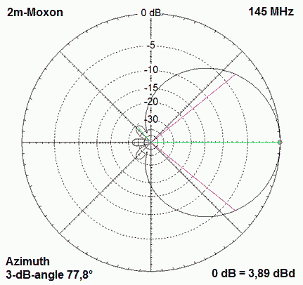
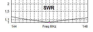
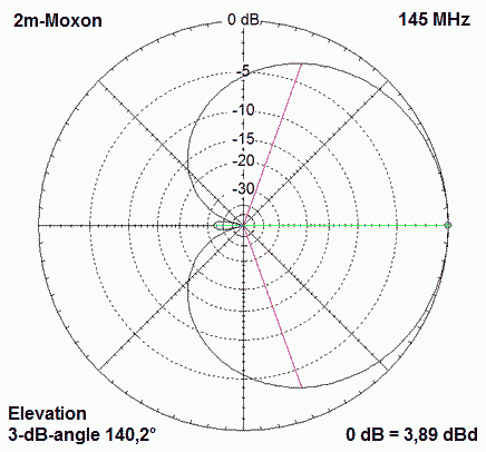
2m Moxon-Beam
The elements of the 2-m-Moxon are made of Aluminium-welding-rods, here with 2,4 mm diameter.
For other diameters see the table below.
The 50-Ohm-coax-cable is connected at the other side of the clamp and wound to choke for a balanced feeding.
The boom is made of a 25-mm-PVC-tube. The element ends are connected together with small insulated tubes for better mechanical stability.


Below: Vertical
Below: Horizontal
Moxon Principles
The Moxon-Beam was introduced by L. Moxon (G6XN) in his book "HF Antennas for all Locations" (RSGB- Publications, Great Britain 1993). This beam is a 2-Element-Yagi with radiator and reflector and reduced size to about 75% of a normal beam. The 2-Element-Yagi with reflector has normally a 0,2-lambda-boom and an impedance of 50 W. The Moxon-beam has a 0,18-lambda-boom and still 50 Ohm. This is a good impedance for wire- beams.The ends of the two elements are bended backward (radiator) or forward (reflector) and act as a capacitive load. That is much better than inductive loading with coils. So we have greater bandwidth and lower losses.Through the reduced size we get a 0,5-0,7 dB lower gain than with a fullsize beam.
This type of a 2-Element-Yagi has an unbelievable F/B-ratio on the design frequency of >= 30 dB. That is higher than with any other 2-Element-Beam.
The gain is higher on the beginning of the band and lower at the end. The bandwidth for a SWR < 1,5 is great enough for the range of 28,0-28,7 and 21,0-21,45 MHz if the beam is built up with aluminium tubes. Wire-beams of the Moxon-type have a smaller bandwidth.
The design frequency should be for a frequency 1/3 from the beginning of the band, because the SWR raises more below the design frequency. For example look for the SWR of a tube-Moxon for the 15-m-band:
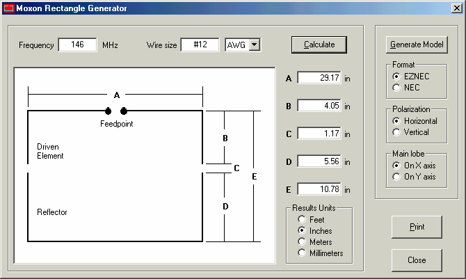
To assist you in calculating the correct dimensions for the Moxon antenna, you can download a Moxon Calculator (Windows only).
